
22 May RC Robot – Part 1
Most of robotic platforms use differential drive as opposed to Ackermann steering, as the differential drive has the leverage of zero-turn-radius that enables high maneuverability

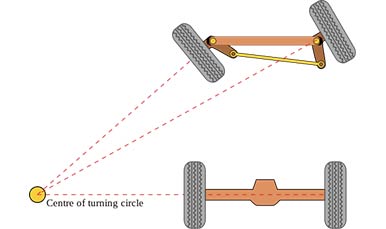
Ackermann Steering
When designing a control scheme for the Ackermann steering, you have two motors; one is used for drive, the other is for steering. So the drive and the steering are separate.

Differential Drive
While in a differential drive, you have both motors responsible for steering and driving. So the steering and driving is actually a function of both motor speeds.
Usually, for controlling a vehicle you implement some sort of joystick to enable intuitive control as the one shown in the figure. These joysticks are usually formed of two variable resistors fixed perpendicular to each other and by changing the stick position, the adjacent resistor value would change.

PlayStation Joystick

Joystick Axis
Again, for Ackermann steering, the Y-axis is used to control the drive and the X-axis is used to control the steer, witch is pretty much straight forward. While for differential drive, it’s really tricky as the Y-axis should control both motors and keep them at the same speed, and the X-axis should also control both motors and keep them at different directions, and this is when the problem arises.
The Problem
The following chart represents the relation between the stick position and the direction & speed of each motor, given that the red arrow represents the left motor, and the blue arrow represents the right motor.

Differential Drive Motor directions
The problem arises when we try to implement the following chart in code, as I already mentioned before the Y-axis controls the motion forward and backward using both motors and the X-axis controls the rotation which also needs both motors. Implementing such a chart to directly code is really a big mess (and I’ve gone through it many times), there will be a lot of IF statements with thresholds, a real mess, and I don’t like my code to be a mess. So I had to think of something to simplify the implementation and use as less code as possible.
First, I had a thought about rotating the joystick by 45 degrees, and using the newly rotated axes to  control the motors by assigning each axis to a single motor as in the following chart. So the green lines represent the new axes after the rotation, assuming the positive ends of the axes are pointing upwards. This simplifies the implementation a lot as every motor is a directly assigned to a single axis.

Differential Drive Motor directions after rotating the joystick 45 degrees
This solves the code complexity problem for me, but still raised two other problems.
First, what if the remote control is already fixed like the one in the image and you can’t rotate the joystick easily?

XBOX controller

Spektrum dx6i RC controller
Second, In most joysticks, the tension on the X-axis and the Y-axis are not identical, this means that moving the stick upward will not be easy as it will always tilt towards the axis with less tension, making it harder for the pilot to control the vehicle.
To solve those problems I had to get back to the basics :p
I thought about axes rotation
X' = X Cos(theta) + Y Sin(theta)

Y' = -X Sin(theta) + Y Cos(theta)
Using these formulas, I no longer needed physically rotating the joystick, hence solving the last two problems, as I will mathematically rotate them.
Implementing the formulas, the
X & Y variables represents the reading from the X & Y axes consecutively, X’ & Y’represents the signals to the left and right motor, and theta should be 45 degrees or PI/4.
But that’s not all, if you’ve worked with a differential drive platform before you’ll know that when moving the forward the slightest difference between the motor speeds will cause the vehicle not to follow a straight line.
By implementing the formulas I’ve just explained, this can easily be fixed using an additional variable resistor to correct the angle (theta) ?
That’s all for now, I hope this helps you in anyway.