
22 May RC Robot – Part 3
If you already read Controlling your RC Robot – Part 1 – Intro and Controlling your RC Robot – Part 2 – Doing the math you’d probably have the full picture of how the implementation should go.
Yet, I’ve been asked many times about the code implementation, so here it goes.
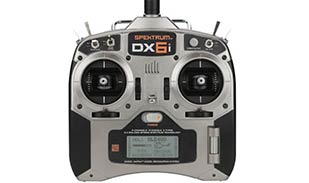
We will be discussing an Arduino implementation, here is the full code that I wrote to control a Rover 5 using a Spectrum DX6i
const int pinM1s = 3;

const int pinM1d = 4;

const int pinM2s = 5 ;

const int pinM2d = 7;

const int pinM3s = 11;

const int pinM3d = 8;

const int pinM4s = 6;

const int pinM4d = 12;
const int AIL = A2;
const int ELE = A3;
const int MIN = 1070;
const int MAX = 1880;
void setup()
{
motorPinSetup(pinM1d, pinM1s);
motorPinSetup(pinM2d, pinM2s);
motorPinSetup(pinM3d, pinM3s);
motorPinSetup(pinM4d, pinM4s);
pinMode(AIL, INPUT);
pinMode(ELE, INPUT);
Serial.begin(115200);
}
void loop()
{
int a = constrain(map(pulseIn(AIL, HIGH),MIN,MAX,-12,12),-12,12);
int e = constrain(map(pulseIn(ELE, HIGH),MIN,MAX,-12,12),-12,12);
float theta = (PI * 45.0 / 180.0) ;
int x = constrain(a * cos(theta) + e * sin(theta),-8,8);
int y = constrain(-a * sin(theta) + e * cos(theta),-8,8);
Serial.print(x);
Serial.print(” – “);
Serial.println(y);
moveRobot(!(x>=0), map(abs(x),0,8,0,255), !(y>=0), map(abs(y),0,8,0,255));
}
void motorPinSetup(int dir, int spd)
{
pinMode(dir, OUTPUT);
pinMode(spd, OUTPUT);
}
void moveMotor(int dirPin,boolean dir, int spdPin, byte spd)
{
digitalWrite(dirPin, dir);
analogWrite(spdPin, spd);
}
void moveRobot(boolean lDir, byte lSpd, boolean rDir, byte rSpd)
{
moveMotor(pinM3d, !lDir, pinM3s, lSpd);
moveMotor(pinM4d, lDir, pinM4s, lSpd);
moveMotor(pinM1d, !rDir, pinM1s, rSpd);

moveMotor(pinM2d, rDir, pinM2s, rSpd);

}

void stopRobot()

{

moveRobot(LOW,0,LOW,0);

}
Now let’s break down the code. This program is built around the following lines
int a = constrain(map(pulseIn(AIL, HIGH),MIN,MAX,-12,12),-12,12);

int e = constrain(map(pulseIn(ELE, HIGH),MIN,MAX,-12,12),-12,12);

float theta = (PI * 45.0 / 180.0) ;
int x = constrain(a * cos(theta) + e * sin(theta),-8,8);

int y = constrain(-a * sin(theta) + e * cos(theta),-8,8);
The first two lines reads the PWM signal from the receiver channels and scales it from -12 to 12.
The third line calculates the theta, where 45.0 is the rotation angle. Here the angle is constant, but we can change it to float theta = (PI * map(analogRead(POT),0,1023,0,180) / 180.0) ; so that the rotation angle is taken from a variable resistor, this will allow us to correct the rotational angle without the need to reprogram the controller.
The last two lines are used to calculate the final speeds and direction for the right and left motors.
There you are, if you have any questions please don’t hesitate to drop a line or contact me directly ?